Operation Blackout — Enterprise Campus Network Design and Implementation
Enterprise campus network designed and implemented in Cisco Packet Tracer, featuring departmental VLANs, router-on-a-stick, LACP EtherChannel, Spanning Tree Protocol, SSH management and Layer 2 security.
About this project
# Project Overview
Operation Blackout is a Cisco Packet Tracer enterprise campus network designed to demonstrate segmented departmental networks, inter-VLAN routing, centralized DHCP, resilient switching, secure device management, and Layer 2 security controls.
The project was built and tested in Cisco Packet Tracer. Its objective was to demonstrate how an enterprise LAN can be designed, configured, verified, and troubleshot using practical networking techniques.
# Objectives
- Design an enterprise campus topology using a router, core switch, and access switches.
- Segment departments and services using VLANs.
- Implement inter-VLAN routing using router-on-a-stick.
- Configure DHCP for departmental clients.
- Configure an LACP EtherChannel between switches.
- Apply Spanning Tree Protocol root-bridge selection.
- Restrict trunk links to required VLANs.
- Configure SSH for switch management.
- Apply switch port security to end-user access ports.
- Configure management SVIs for switch administration.
- Verify connectivity and investigate a VLAN-related trunking fault.
# Network Topology
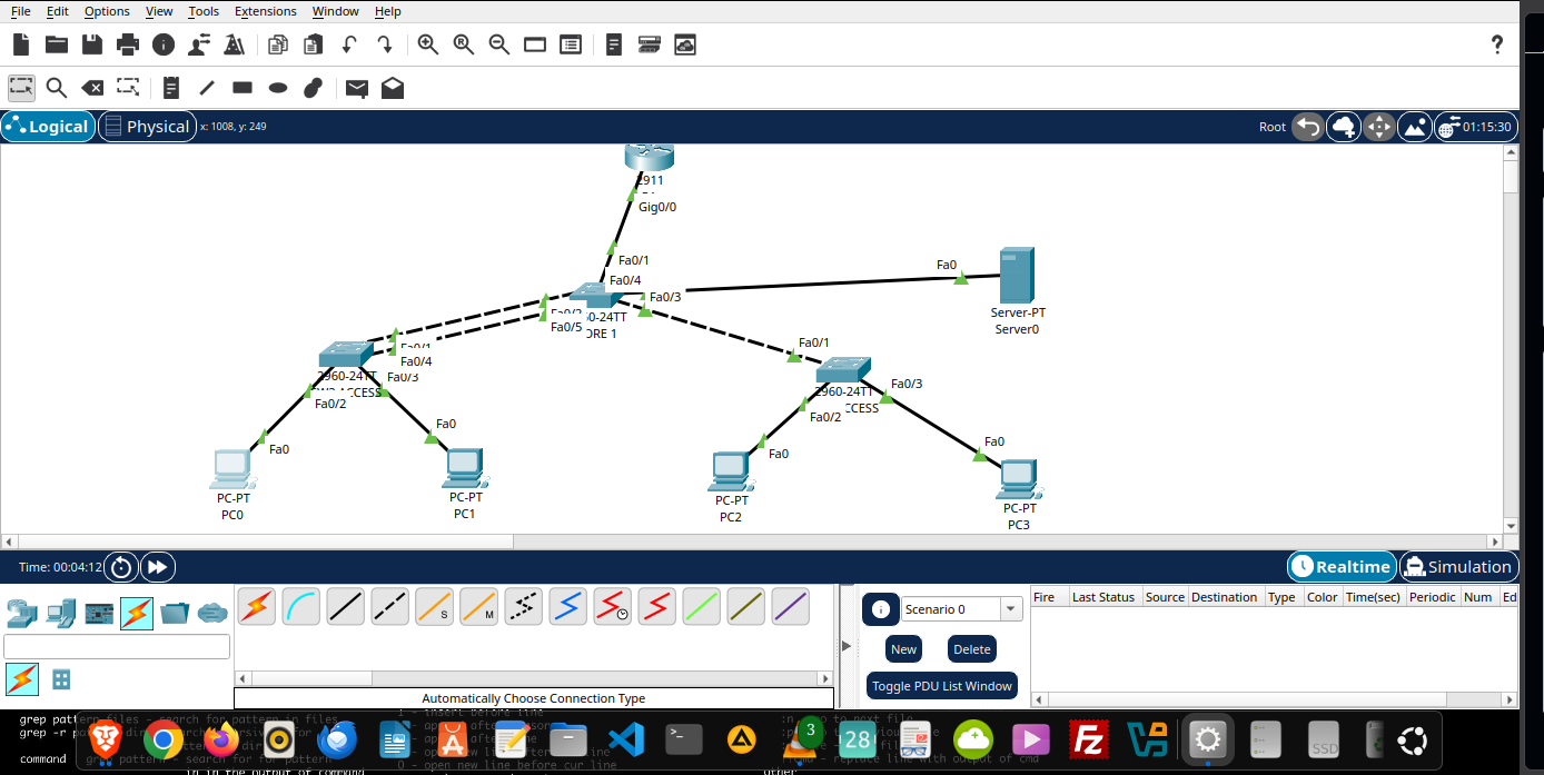
The network consists of:
- **R1-BLACKOUT:** Router providing inter-VLAN routing and DHCP.
- **SW1-CORE:** Core switch providing VLAN trunking, EtherChannel aggregation, and the intended STP root role.
- **SW2-ACCESS:** Access switch connecting Administration and Finance clients.
- **SW3-ACCESS:** Access switch connecting IT and Staff clients.
- **PC0–PC3:** Four departmental end-user devices.
- **Server0:** Server in the dedicated Servers VLAN.
The router connects to SW1-CORE using a trunk link. SW1-CORE connects to SW2-ACCESS through an LACP EtherChannel and to SW3-ACCESS through a trunk link.
See the [Topology](https://github.com/GerradChibuye/infra-labs/blob/main/project-01-operation-blackout/topology.md) and [Addressing Plan](https://github.com/GerradChibuye/infra-labs/blob/main/project-01-operation-blackout/addressing-plan.md).
# VLAN and IP Addressing
| VLAN | Name | Subnet | Default Gateway |
|---|---|---|---|
| 10 | ADMIN | 192.168.10.0/26 | 192.168.10.1 |
| 20 | FINANCE | 192.168.10.64/26 | 192.168.10.65 |
| 30 | IT | 192.168.10.128/26 | 192.168.10.129 |
| 40 | STAFF | 192.168.10.192/26 | 192.168.10.193 |
| 50 | SERVERS | 192.168.11.0/27 | 192.168.11.1 |
| 99 | MANAGEMENT | 192.168.11.32/27 | 192.168.11.33 |
Departmental clients in VLANs 10, 20, 30, and 40 receive IPv4 configuration through DHCP. The server and switch management interfaces use statically assigned addresses.
# Key Implementations
## 1. VLAN Segmentation
Six VLANs separate departmental, server, and management traffic. This creates distinct Layer 2 broadcast domains and provides a foundation for applying network policies.
## 2. Inter-VLAN Routing
Router-on-a-stick is implemented on R1-BLACKOUT using 802.1Q subinterfaces. Each subinterface provides the default gateway for its corresponding VLAN.
## 3. DHCP
The router provides DHCP pools for the four departmental VLANs. Gateway addresses and reserved ranges are excluded from dynamic allocation.
## 4. LACP EtherChannel
SW1-CORE and SW2-ACCESS use LACP to bundle two physical links into Port-channel1. The bundle provides increased aggregate link capacity and continued connectivity if one member link fails, provided the remaining member is operational.
## 5. Spanning Tree Protocol
PVST is enabled. SW1-CORE is configured with a preferred root-bridge priority for VLANs 10, 20, 30, 40, 50, and 99.
## 6. Trunk VLAN Restrictions
Trunk links and Port-channel1 are configured to carry the required VLANs: 10, 20, 30, 40, 50, and 99.
## 7. SSH Management
SSH version 2 and local user authentication are configured on the switches. The switch VTY lines are configured to accept SSH rather than Telnet.
## 8. Access-Port Security
Port security is applied to the four departmental end-user ports using sticky MAC learning and the restrict violation action. The intended limit is one learned MAC address per protected port.
## 9. Unused-Port Administration
Selected unused access ports are administratively shut down. The exact status of unused interfaces varies by switch and is documented in the configuration references where applicable.
# Verification and Troubleshooting
The lab was tested for:
- DHCP address allocation to departmental clients.
- Inter-VLAN connectivity.
- Reachability of Server0.
- Reachability of switch management addresses.
- EtherChannel formation and recovery after a member-link interruption.
- STP root-bridge selection.
- Trunk VLAN membership.
- SSH access to switches.
- Port-security status on protected access ports.
A significant fault occurred when VLAN 20 was accidentally omitted from the allowed VLAN list on Port-channel1. This prevented the affected cross-switch communication. Correcting the allowed VLAN list restored connectivity.
See the [Verification Results](https://github.com/GerradChibuye/infra-labs/blob/main/project-01-operation-blackout/verification.md) and [Troubleshooting Case Study](https://github.com/GerradChibuye/infra-labs/blob/main/project-01-operation-blackout/troubleshooting.md).
# Documentation and Configuration References
- [Addressing Plan](https://github.com/GerradChibuye/infra-labs/blob/main/project-01-operation-blackout/addressing-plan.md)
- [Topology](https://github.com/GerradChibuye/infra-labs/blob/main/project-01-operation-blackout/topology.md)
- [Verification Results](https://github.com/GerradChibuye/infra-labs/blob/main/project-01-operation-blackout/verification.md)
- [Troubleshooting Case Study](https://github.com/GerradChibuye/infra-labs/blob/main/project-01-operation-blackout/troubleshooting.md)
- [Configuration Capture Guide](https://github.com/GerradChibuye/infra-labs/blob/main/project-01-operation-blackout/configs/configuration-capture-guide.md)
- [Router Configuration Reference](https://github.com/GerradChibuye/infra-labs/blob/main/project-01-operation-blackout/configs/R1-BLACKOUT.md)
- [Core Switch Configuration Reference](https://github.com/GerradChibuye/infra-labs/blob/main/project-01-operation-blackout/configs/SW1-CORE.md)
- [Access Switch 2 Configuration Reference](https://github.com/GerradChibuye/infra-labs/blob/main/project-01-operation-blackout/configs/SW2-ACCESS.md)
- [Access Switch 3 Configuration Reference](https://github.com/GerradChibuye/infra-labs/blob/main/project-01-operation-blackout/configs/SW3-ACCESS.md)
- [Evidence Directory](https://github.com/GerradChibuye/infra-labs/blob/main/project-01-operation-blackout/evidence/README.md)
The configuration references document important settings and interface roles. They are sanitized documentation, not replacements for the original Packet Tracer `.pkt` file.
# Skills Demonstrated
- IPv4 subnetting and VLSM
- VLAN configuration and segmentation
- IEEE 802.1Q trunking
- Router-on-a-stick
- DHCP configuration
- LACP EtherChannel
- PVST root-bridge selection
- SSH device administration
- Switch port security
- Network troubleshooting and verification
- Technical documentation and version control
# Project Files
The Packet Tracer topology is stored in `operation-blackout-campus.pkt`. Open it with Cisco Packet Tracer to inspect the topology and reproduce the lab.
# Scope and Limitations
This is a simulated campus network. The project demonstrates configuration and verification in Packet Tracer; it does not establish production deployment, measured throughput, or physical hardware performance.
The lab does not claim implementation of dynamic routing, redundant routers, a dedicated firewall, or a production monitoring system.
# Author
**Gerrad Chibuye**
Infrastructure Engineering | Networking | Linux and Systems
[GitHub Profile](https://github.com/GerradChibuye)